- 导读
多硫化锂(LiPSs)的穿梭效应、硫氧化还原反应动力学慢、导电性差等问题阻碍了锂硫电池的商业化发展。通过使用木质素基碳纳米纤维(CNF)原位热诱导还原策略,调制了p-block Bi 6p轨道的电子构型。这种方法使得δ-Bi2O3径向梯度复相结构演变,形成了高密度的富氧空位的异质结网络集群(δ-Bi2O3-OVS/Bi@CNFS),有效地优化了LiPSs的化学吸附,提高了硫氧化还原反应的动力学。基于δ-Bi2O3-OVS/Bi@CNFS,构筑了容量为1.8 Ah的高能量密度(377 Wh kg−1)锂硫软包电池,并成功应用于无人机飞行,突出了其实际应用的潜力。本工作阐明了p-lock金属氧化物原位热致径向-梯度复相演结构化的机理,以及6p轨道电子调制对硫氧化还原反应的影响。
- 成果掠影
大连工业国家级人才青年托举胡顺友联合莆田学院易明杰教授/广西大学孙少超/辽宁大学颜强/清华大学杨洋/大连工业大学肖领平&孙润仓教授提出了一种新的、可持续的电纺技术,通过将制浆造纸黑液中的木质素与原位碳热还原技术相结合,创建了径向梯度δ-Bi2O3-OVS/Bi@CNFS异质界面。通过独特的方式调节LiPSs的Bi 6p轨道电子占位(6s26p2)和p带中心来优化LiPSs的化学吸附,加快了LiPSs的氧化还原动力学,缓解了LiPSs的穿梭效应。实验结果和密度泛函理论计算证实,LiPSs的催化活性来源于Bi 6p轨道在异质界面的填充度和Bi3+/Bi0双活性中心,它们协同增强了LiPSs的电荷转移和氧化还原动力学。优化后的锂硫电池表现出优异的性能,在0.2 C下实现了1439 mAh g−1的高初始容量,在1.0 C下保持了超过1000次的超长循环稳定性,每次循环的衰减率为0.039%。值得注意的是,组装的1.8 Ah软包电池在贫电解液条件下提供了377Wh kg−1的高重量能量密度(E/S比率=2.8 μL mg−1)。本研究通过CNFs介导的原位径向热致p-block金属氧化物径向梯度复相结构演变,调节p-轨道电子结构和p-带中心,促进中间体的动态化学吸附和快速催化转化,建立了p-block金属催化剂的设计范式,从而为SRR以外的多电子反应体系铺平了道路。
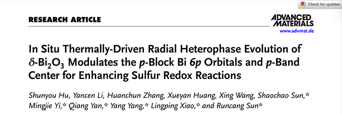
该成果以题目“In Situ Thermally-Driven Radial Heterophase Evolution of δ-Bi2O3 Modulates the p-Block Bi 6p Orbitals and p-Band Center for Enhancing Sulfur Redox Reactions”发表在国际顶刊/中科院一区期刊Advanced Materials上,IF为26.8。
三、核心创新点
其核心创新点在于通过一种新颖的原位热驱动径向梯度复相结构演化策略,精准调控了p区金属铋(Bi)的6p轨道电子占据状态和p带中心,从而显著提升了锂硫电池中多硫化物的转化动力学。具体而言,研究团队利用造纸工业的副产品-黑液木质素作为碳源,通过静电纺丝、溶剂热反应和原位碳热还原技术,成功构建了富含氧空位、具有径向梯度异质结结构的高密度复合材料(δ-Bi₂O₃-Ovs/Bi@CNFs)。这一独特的结构设计是创新的关键:在碳纳米纤维上,金属Bi与δ-Bi₂O₃形成了从内到外的径向异质结网络,同时引入了大量氧空位。这种结构不仅通过构建内建电场(BIEF)极大地提高了材料的本征电导率,更重要的是,它通过热还原过程精确地将Bi的电子构型从δ-Bi₂O₃中的Bi³⁺ (6s²6p⁰) 调整为中间价态 Biᵠ (0<φ<3, 6s²6p²),实现了对6p轨道的部分填充。
四、数据概览
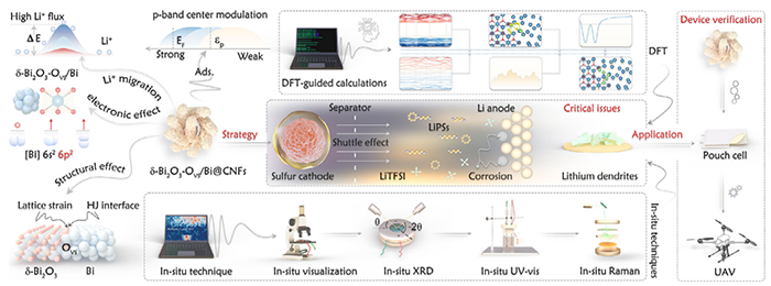
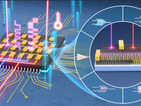
Figure 1. Overall workflow diagram illustrating the features ofthe orbital electronic configuration, crystal structure, DFT analysis, and device validation.
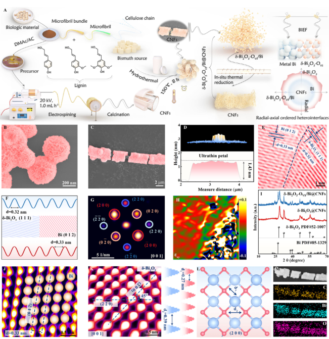
Figure 2. A) Schematic illustration of the fabrication process for the δ-Bi2O3-OVS/Bi@CNFS. SEM images of δ-Bi2O3 B) and δ-Bi2O3-OVS/Bi@CNFS C). D) AFM images and corresponding height profile of δ-Bi2O3-OVS/Bi@CNFS. HRTEM images E), inverse fast-Fourier-transform lattice images F), SAED pattern G), and geometric phase analysis H) of δ-Bi2O3-OVS/Bi@CNFS. I) XRD pattern of the composites. Spherical aberration-corrected HAADF-STEM images of Bi J) and Bi2O3 K) and corresponding crystal structure L). M) Elemental mapping images of δ-Bi2O3-OVS/Bi@CNFS.
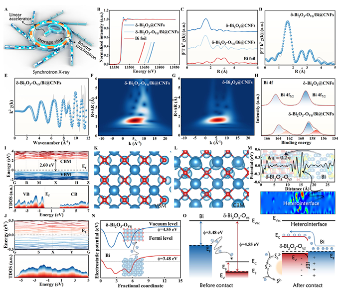
Figure 3. A) Schematic diagram of the synchrotron radiation. B) Normalized XANES of Bi L3 edge. C) FT-EXAFS spectra. Fitting curves of Bi L3 edge for
δ-Bi2O3-OVS/Bi@CNFS at R space D) and k space E). WT contour plots of δ-Bi2O3-OVS/Bi@CNFS F) and δ-Bi2O3@CNFs G). H) Bi 4f high-resolution XPS. Energy band diagram and DOS of δ-Bi2O3@CNFs I) and δ-Bi2O3-OVS/Bi@CNFS J). The spatial charge densities of VBM K) and CBM L) of δ-Bi2O3. M) Charge density difference of δ-Bi2O3-OVS/Bi@CNFS. N) Schematic diagram of work functions of Bi and δ-Bi2O3-OVS. O) Energy band diagrams of Bi and δ-Bi2O3-OVS before and after contact.
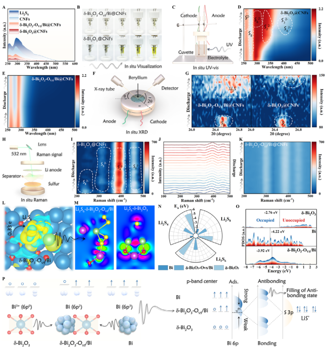
Figure 4. A) UV absorbance spectra of the Li2S6 solutions. B) Optical images of Li||S batteries during the discharge process. Schematic illustration of in situ UV–vis C) and corresponding spectra D,E). Schematic illustration of in situ XRD F) and corresponding spectra G). Schematic illustration of in situ Raman H) and corresponding spectra I–K). L,M) The charge density difference and corresponding calculated volume slices of Li2S6 adsorption system. N) Adsorption energy between LiPSs and catalysts. O) p-band centers of Bi-based composites. P) Schematic of the mechanism linking the Bi 6p orbital electronic configurations to the chemical
adsorption of LiPSs.
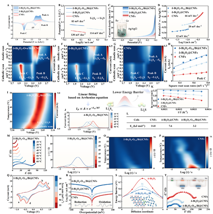
Figure 5. A) CV profiles and corresponding B) Tafel plots (LiPSs → Li2S). LSV plots C) and corresponding Tafel plots D). E–G) Contour plots of CV patterns at different scan rates. H) Fitting line between IP and v0.5 at various scan rates. I) Contour plots of CV patterns at different temperatures. J) Enlarged CV curves (LiPSs → Li2S). K) Fitting line between lnI and 1/T. L) Ea for the deposition of Li2S. In situ EIS-DRT images M–P) of Li||S batteries. CV curves Q) and Tafel plots R) for Li2S6 symmetric cells. S) Energy barrier of Li+ diffusion. T) EIS of Li2S6 symmetric cells.
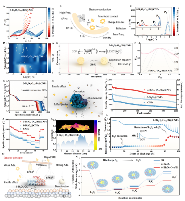
Figure 6. A) In situ EIS of the cell during the discharging process. B) Schematic illustration of the electrochemical behavior across different frequency ranges. In situ DRT plots C) and the corresponding 2D intensity mapping D). E) Kinetic assessment using PITT measurements. F) Dimensionless current-time transient during Li2S deposition process. G) Galvanostatic discharge profiles of δ-Bi2O3-Ovs/Bi@CNFs-based cell. H) Schematic illustration of lithium metal corrosion. I) Cycling performance of the cells at 1.0 C. J) Rate performance of the Li||S batteries. K) AFM images of Li anode after cycling. L) GITT curves and corresponding resistance. M) Schematic illustration of enhancing Li||S batteries with δ-Bi2O3-Ovs/Bi@CNFs. N) Gibbs free energy for SRR.
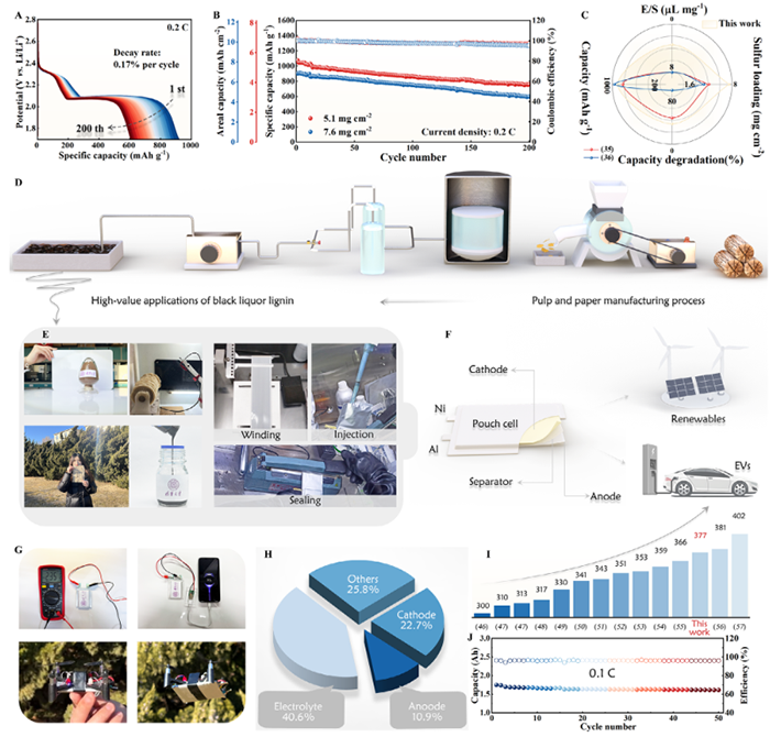
Figure 7. Discharge profiles A) and cycling performance B) of δ-Bi2O3-Ovs/Bi@CNFs-based cells with high sulfur loadings. C) Comparisons of high-sulfur Li||S batteries from previous studies. D) Schematic illustration of the pulping and papermaking process. E) Digital images of the Li||S pouch cell fabrication process. Application prospects of Li||S pouch cells F) and their practical utilization in mobile phone and drone technologies G). H) Composition percentages of the pouch cell. I) The performance comparison between this work and previously reported studies. J) Cycling per-formance of the pouch cell.
五、成果启示
这项研究为锂硫电池及能源材料设计提供了关键启示:通过精准调控p区金属的轨道电子构型,而非传统的d区金属,可高效优化催化剂的吸附-催化行为。利用木质素等生物质废弃物制备高性能电极,实现了“变废为宝”的绿色循环。其首创的径向梯度异质结结构结合氧空位,协同提升了导电性与反应动力学,为解决多硫化物穿梭和转化缓慢难题提供了新范式。该策略不仅推动了锂硫电池的实用化进程,更启示了p区金属催化剂在多电子反应体系中的广阔前景,为下一代储能材料设计指明了方向。