背景介绍
硫化氢(H₂S)及其水溶液中的硫离子(S2⁻)是高毒性、强腐蚀性的含硫污染物,对生态环境、人体健康及工业安全构成严重威胁。在含硫矿物(如闪锌矿、硫铁矿等)及复合固废(如废CRT荧光粉、废钠硫电池、废锂硫电池等)处理过程中,为实现金属等有价组分的分离提取,常需采用酸浸、热处理等工艺环节。此类过程中含硫组分易与试剂或环境反应,释放出H2S气体或产生含S2⁻废水。类似地,在天然气净化、炼油、合成气制备等传统工业中也面临大量H2S排放与治理难题。当前主流的Claus法等脱硫技术虽能实现硫回收,但普遍存在能耗高、水耗大、产物附加值低等局限。值得注意的是,硫本身作为一种重要的基础化工原料,开发能够将含硫污染物(H2S/S2⁻)直接、高效转化为高价值产品的技术,对于推动含硫废弃物的资源化利用与硫元素循环具有重要意义。
电化学硫化物氧化反应(SOR)可在温和条件下实现硫化物向单质硫的转化,并协同产氢。然而,其在实际应用中仍面临关键挑战:硫物种与金属活性位点之间的强相互作用虽有利于反应活化,却不可避免地导致表面硫沉积与催化剂中毒失活;同时,多硫中间体的稳定吸附进一步加剧活性位点覆盖,形成“高活性—低稳定性”的内在矛盾,严重制约其长期稳定运行。
针对上述含硫物料处理过程中H2S/S2⁻排放与资源化难题,北京工业大学吴玉锋、王长龙团队在《Advanced Materials》期刊发表了题为《Pulsed electrolysis prevents sulfur poisoning for sustained sulfide valorization》的研究成果。该工作创新性地提出了一种基于脉冲电解(PE)的动态微环境调控策略,通过对界面反应环境进行周期性重构,有效抑制了硫沉积所引发的催化剂钝化失活。这一电化学转化体系有望与现有火法-湿法联合回收工艺实现深度融合,进而构建一条完整的闭环循环经济链条:即在实现金属等有价组分提取的同时,将伴生的含硫中间体同步转化为高纯氢与单质硫。该路径不仅将含硫废弃物重塑为可服务于新能源与化工领域的重要资源,同时可将产出的高纯氢气反哺至冶金与分离过程,有效降低对外部能源与化学品的依赖,为含硫矿物及复合固废的绿色高值化利用提供了新的技术支撑。
研究创新点
1. 提出“脉冲电解驱动的动态微环境工程”新策略:突破传统恒电位电解模式,通过高电位/开路电位的周期切换,实现界面反应环境的动态调控,从机制上重构反应路径。
2. 破解SOR中“活性—稳定性”内在矛盾:利用脉冲调控促进硫在低电位阶段快速脱附,破解催化剂中毒难题,在保持高活性的同时显著提升体系长期稳定性,实现二者的协同优化。
3. 构建“催化剂设计—反应过程调控”协同优化:通过Sc掺杂NiFe-LDH调控关键中间体吸附能,耦合脉冲电解,首次实现材料层面与运行策略的协同设计。
4. 实现高效、低能耗的硫化物资源化转化体系:在温和条件下实现硫化物向单质硫的高效转化(99.8%效率、>500 h稳定运行),并耦合高纯氢气生成,减污降碳增值。
5. 打通含硫矿物及复合固废的资源闭环路径:提出“含硫废弃物→高纯硫+氢气”的高值转化路线,验证了体系在复杂工况下的稳定性,构建了“污染治理—资源再生—能源回用”闭环循环经济体系。
图文解析
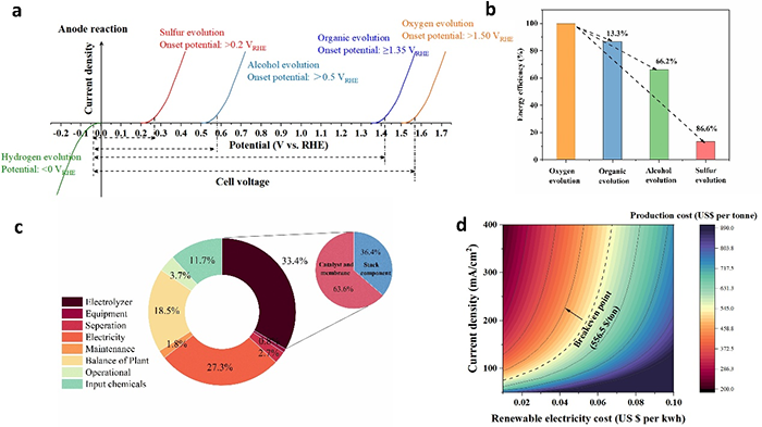
图1. (a) Comparison of various anodic reactions with water electrolysis; (b) The reduction rate in energy efficiency compared to OER; (c) The subdivided cost of the entire process for SOR at the given electricity price of US$0.03 per/kWh; (d) Levelized cost of co-productions hydrogen and sulfur via SOR, as a function of current density and electricity cost.
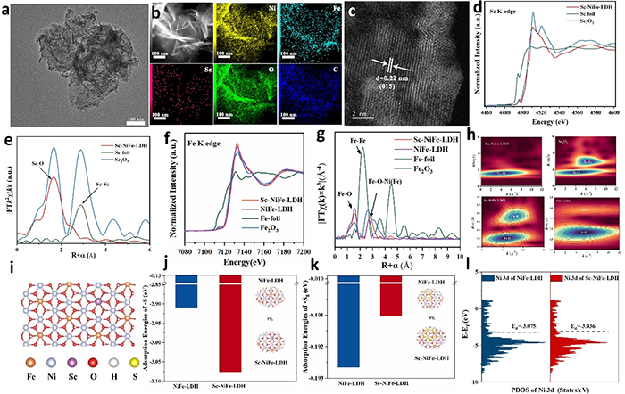
图2. (a) TEM image; (b) AC HAADF-STEM image of Sc-NiFe LDH and the corresponding elemental mappings; (c) HRTEM; (d) Normalized Sc K-edge XANES and (e) Fourier transform of the EXAFS spectra of Sc-NiFe-LDH and the references (Sc foil, Sc2O3); (f) Normalized Fe K-edge XANES and (g) Fourier transform of the EXAFS spectra of Sc-NiFe-LDH and the references (Fe foil, Fe2O3, NiFe-LDH); (h) WT-EXAFS contour plots of the Sc2O3, NiFe-LDH, Sc-NiFe-LDH; (i) Model of Sc-NiFe-LDH; DFT calculated adsorption energies (j) S2-; (k) S8; (l) The projected density of states (PDOS).
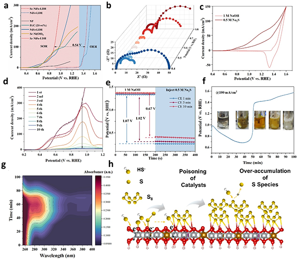
图3. (a) LSV curves of SOR for Sc-NiFe-LDH and control electrodes. (b) Nyquist plots at various potentials; (c) CV curves of Sc-NiFe-LDH in 1 M KOH with and without 0.5 M Na2S; (d) LSV curves of Sc-NiFe-LDH electrode in 1 M NaOH with Na2S at different scan times; (e) Open-circuit potential curves of Sc-NiFe-LDH after CE with different times in NaOH, with Na2S being injected subsequently. (f) Chronopotentiometric curves of Sc-NiFe-LDH at 100 mA/cm2; (g) UV-vis spectra during SOR; (h) Schematic illustration of CE-SOR over Sc-NiFe-LDH.
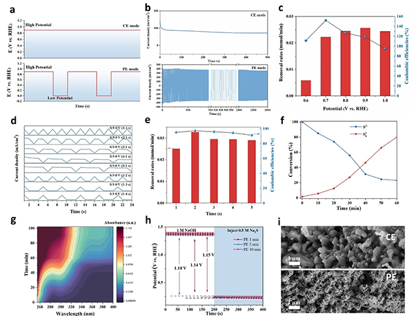
图4. (a) Output potentials and (b) Chronoamperometric curves at CE and PE modes. (c) Removal rates of S2– and coulombic efficiencies under different potentials at CE model; (d) Output potentials of a pulsed square wave with different high and low potential duration times; (e) Removal rates of S2– and coulombic efficiencies at PE model (E0.9 = 1–5 s, E0 = 1 s); (f) Concentration changes of S2– and Sn2– at PE mode (E0.9 = 2 s, E0 = 1 s); (g) UV-vis spectra during SOR; (h) Open-circuit potential curves of Sc-NiFe-LDH at PE model; (i) SEM images of the catalysts after reaction at either CE or PE model.
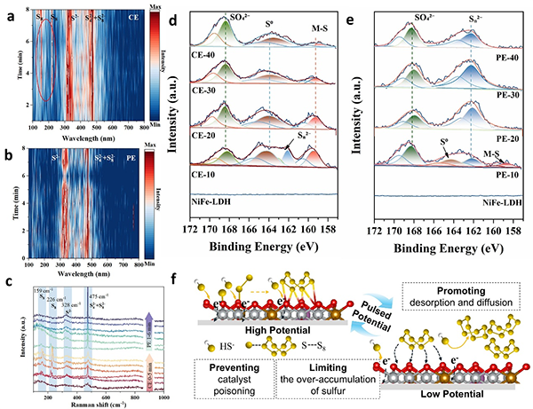
图5. In-situ Raman spectra collected at (a) CE mode; (b) PE mode; (c) CE for 5 min then PE for 6 min; Ex situ XPS spectroscopy of Sc-NiFe-LDH electrode for SOR during the time course of 10 to 40 min at (d) CE mode; (e) PE mode; (f) Schematic illustration of the mechanism of Sc-NiFe-LDH catalyzed SOR at PE mode.
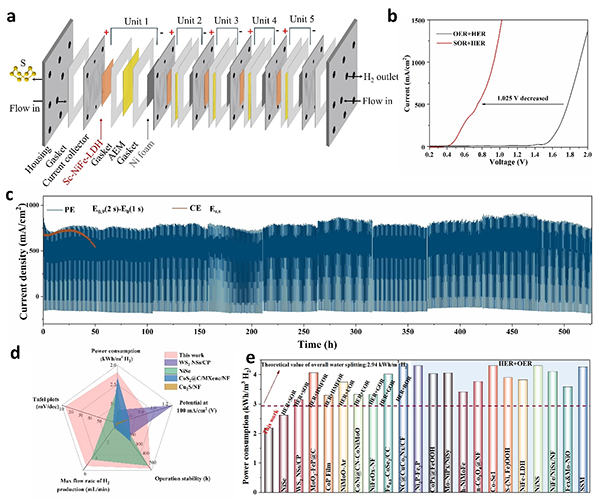
图6 (a) Schematic diagram of stacked MEA system consisting of five stacked modules; (b) LSV curves of Sc-NiFe-LDH in 1 L of 1 M NaOH with or without 1 M Na2S in MEA; (c) Catalyst’s durability tests at PE and CE mode (replacing fresh electrolyte every 52 h); (d) Comparison of the catalytic performances of Sc-NiFe-LDH with the state-of the art electrocatalysts; (e) Comparisons of the power consumptions between Sc-NiFe-LDH and literature-reported muti-functional electrocatalysts.
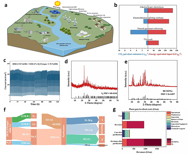
图7 (a) Schematic illustration of the integrated process of sulfide contaminant recycling, sulfur production, and purification; (b) Comparison of a hybrid seawater-SOR electrolyzer system with different hydrogen production techniques in energy equivalent input and CO2 equivalent emission; (c) Durability of Sc-NiFe-LDH for the electrochemical removal of H2S from industrial syngas (2% H2S) in 1 M NaOH solution; (d) XRD of prepared S8; (e) XRD of obtained sodium formate; (f) Sankey diagram for the mass flow of industrial syngas upcycling; (g) SOR profit comparisons before and after sulfur purification.
总结与展望
本工作将脉冲电解(PE)策略与高性能Sc–NiFe-LDH催化剂相结合,从循环经济视角出发,为含硫废弃物的高值化利用开辟了一条全新电化学路径。针对含硫矿物及复合固废处理过程中不可避免产生的H2S气体与含S2-废水,该体系提供了一种将污染物直接转化为资源的闭环解决方案。通过Sc3+掺杂优化中间体吸附能,结合脉冲电位促进硫物种脱附并抑制活性位点过度氧化,二者协同调控界面动态微环境,成功破解了硫化物氧化反应(SOR)中“高活性—低稳定性”的矛盾。该体系实现了99.8%的效率,在2.19 kWh m-3 H2的低能耗下完成硫回收与产氢(能耗较传统碱性水电解降低57.7%),并展现出超过500小时的长期稳定性。以生物基甲酸替代无机酸进行电解液酸化,可获得纯度99.5%的单质硫并联产高附加值甲酸钠。
展望未来,该技术路线为含硫污染物的资源化提供了重要支撑,具有良好的发展前景。但需指出,目前相关研究仍处于实验室层面,上述数据在工业放大过程中可能因传质、电极结构、长期运行工况等因素发生变化。因此,走向工业化仍有许多有待深入研究的工作,后续需进一步开展中试验证与系统集成研究。