- 导读
本研究成功合成了一种嵌入氮、磷、氟共掺杂碳基体中的碲空位镍钴碲化合物异质结材料(NiTe1-x-CoTe1-x/NPFC)。在NiTe1-x-CoTe1-x异质结构中,镍碲化合物与钴碲化合物之间的电子协同效应诱导了局部电荷重新分布,不仅提升了材料的金属导电性,显著降低了氢吸附能,还增强了其对析氢反应的本征催化活性。在超级电容器测试中,该异质结构进一步为氧化还原反应提供了更丰富的活性位点和更快速的离子/电子传输路径,从而在提升赝电容贡献的同时,实现了功率密度与能量密度的协同增强。此外,杂原子掺杂与空位构筑策略能够暴露更多不饱和配位原子作为催化活性位点,增强材料导电性,进而持续推动电化学性能的提升。正因如此,NiTe1-x-CoTe1-x/NPFC在析氢反应和超级电容器测试中均展现出卓越的性能。本研究为开发具有富碲空位的碲化物异质结及氮磷氟共掺杂碳复合材料提供了新的设计思路,该策略也可拓展应用于其他电极材料与电催化剂体系。
- 成果掠影
近日,莆田学院易明杰教授,黄建辉教授和哈尔滨工业大学的张嘉恒教授,针对低导电性、离子扩散缓慢和反应活性位点少等弊端,研究合理地采用碲空位、异质界面和杂原子掺杂等方式,通过简单的离子液体辅助水热法和煅烧法合成了富含Te空位的NiTe-CoTe异质结与N、P、F共掺杂碳的复合物(NiTe1-x-CoTe1-x/NPFC)。DFT表明,Te空位、异质结以及N、P、F的掺杂能够引起材料表面电荷重新分布,优化了物理性质,提升了材料对H*/OH–的吸附能。因此,NiTe1-x-CoTe1-x/NPFC在碱性溶液中对HER表现出优异的活性。同时,NiTe1-x-CoTe1-x/NPFC作为正极材料在柔性固态超级电容器中,于15.90 kW kg-1的功率密度下具有57.9 Wh kg-1的优异能量密度。总体而言,本研究提供了对具有富含碲空位的碲化物异质结和N、P、F掺杂碳复合材料设计的重要见解,这种优化方式也可适用于其他类型的电极材料和电催化剂。
该成果以莆田学院为第一单位以题目“Ionic-liquid-assisted synthesis of NiTe/CoTe heterostructure with Te vacancies in N, P, F co-doped hollow carbon nanorods for efficient alkaline hydrogen evolution and high-performance flexible supercapacitors”发表在中科院一区期刊Rare Metals,影响因子为11。
三、核心创新点
该研究核心创新点在于采用离子液体辅助水热-煅烧法,成功构建了具有丰富Te空位的NiTe/CoTe异质结,并将其封装于N、P、F共掺杂的中空碳纳米棒中,实现了材料在碱性析氢反应和柔性超级电容器中的双重高效性能,揭示了异质结、Te空位与杂原子掺杂协同增强电催化与储能性能的机制,为设计具有Te空位和杂原子掺杂的碲化物异质结电极材料提供了重要的理论依据和实验策略。
四、数据概览

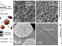
Fig. 1. (A) Schematic illustration of the preparation of NiTe1−x–CoTe1−x/NPFC; SEM images of (B) Te nanorods and (C) Ni(OH)2–Co(OH)2–IL/Te; the (D) TEM image and (E) HAADF‐STEM image of Ni(OH)2–Co(OH)2–IL/Te; the (F) SEM, (G) TEM image, (H) SAED diffraction pattern, (I, J) HRTEM images, (K, L) inverse FFT lattice image and lattice spacing of NiTe1−x–CoTe1−x/NPFC; (M) the schematic illustration of the heterojunction of NiTe1−x and CoTe1−x; (N) mapping of NiTe1−x–CoTe1−x/NPFC.
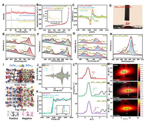
Fig. 2. (A) X‐ray diffraction (XRD) patterns, (B) BET, (C) EPR and (D) water contact angles of NiTe1−x‐CoTe1−x/NPFC; XPS peaks of (E) Co 2p, (F) Ni 2p, (G) Te 3d and (H) C 1s for NiTe1−x–CoTe1−x/NPFC; (I) Electron density difference images of NiTe1−x–CoTe1−x/NPFC. Total density of states (TDOS) of (J) NiTe1−x–CoTe1−x, (K) Ni K‐edge XANES spectra and (L) corresponding FT EXAFS for NiTe1−x–CoTe1−x/NPFC and other materials; WT contour plots (M) Ni foil, (N) NiTe1−x–CoTe1−x/NPFC, and (O) NiTe1−x/NPFC.
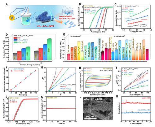
Fig. 3. (A) The schematic of the HER process; (B) LSVs of NiTe1−x–CoTe1−x/NPFC, CoTe1−x/NPFC, and NiTe1−x/NPFC in a 1.0 M KOH solution; (C) the corresponding Tafel plots and (D) corresponding parameters of LSV and Tafel plots; (E) a comparative analysis of overpotentials at 10 and 100 mA cm−2 among NiTe1−x–CoTe1−x/NPFC and other previously reported samples; (F) the estimated amounts of gas produced over NiTe1−x–CoTe1−x/NPFC; (G) EIS of NiTe1−x–CoTe1−x/NPFC in comparison with its reference material; (H) CV curves and (I) Cdl for NiTe1−x–CoTe1−x/NPFC along with other references; (J) The LSV curves before and after 1000th CV tests; (K) the cycling stability of NiTe1−x–CoTe1−x/NPFC after a duration of 100 h at −100 mA cm−2; (L) SEM and (M) XRD analyses conducted after HER in 1.0 M KOH.

Fig. 4. (A) Schematic of the in situ Raman; (B) operando Raman patterns of the 2D color‐filled contour plot of NiTe1−x–CoTe1−x/NPFC; (C) Gaussian fits of three O–H stretching modes (vO−H); (D) in situ Raman spectra of interfacial water at NiTe1−x‐CoTe1−x/NPFC; (E) normalized Raman intensities of vO−H at NiTe1−x–CoTe1−x/NPFC over HER potentials; (F) frequency plot of changes in the vO−H in Raman spectra of interfacial water at original Ru surfaces; (G) schematic diagram of the reaction of NiTe1−x–CoTe1−x/NPFC in alkaline solution and (H) the corresponding free energy profile.

Fig. 5. (A) Schematic representation of the supercapacitor operation; (B) CV spectra for the NiTe1−x–CoTe1−x/NPFC electrode at different scan rates; (C) CV spectra of various samples obtained at 20 mV s−1; (D) galvanostatic charge–discharge (GCD) for NiTe1−x–CoTe1−x/NPFC across a range of current densities; (E) GCD; (F) rate capability; (G) EIS results and (H) stability data of different samples; (I) Specific capacity plot of NiTe1−x–CoTe1−x/NPFC and other reported samples; (J) schematic of the in situ XRD; (K) XRD patterns and (L) operando Raman patterns of the 2D color‐filled contour plot of NiTe1−x–CoTe1−x/NPFC; (M) ball‐and‐stick models of NiTe1−x–CoTe1−x/NPFC, CoTe1−x/NPFC, and NiTe1−x/NPFC after OH* adsorption; (N) EOH− amounts of NiTe1−x–CoTe1−x/NPFC, CoTe1−x/NPFC, and NiTe1−x/NPFC.
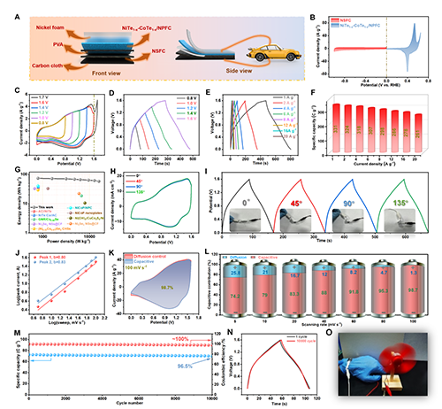
Fig. 6. (A) Structure of the as‐assembled flexible device with the configuration of NiTe1−x–CoTe1−x/NPFC//NSFC; (B) CV curves of NiTe1−x–CoTe1−x/NPFC and NSFC at 20 mV s−1; (C) CV curves of NiTe1−x–CoTe1−x/NPFC//NSFC at various potentials; (D) GCD curves of NiTe1−x–CoTe1−x/NPFC//NSFC at various potentials; (E) GCD curves collected at different current densities; (F) specific capacitance at different
current densities; (G) Ragone plots of the present device and previously reported ones; (H) CV curves at a scan rate of 20 mV s−1 and (I) GCD curves at current density of 4 A g−1 for NiTe1−x–CoTe1−x/NPFC//NSFC, collected during bending; (J) the b‐values for both the cathodic and anodic peaks; (K) CV partitioning analysis demonstrates the capacitive contribution to the total current at 100 mV s−1; (L) normalized ratios of
capacitive capacity contributions at different scan rates; (M) cycling performance and Coulombic efficiency of NiTe1−x–CoTe1−x/NPFC//NSFC at a current density of 4 A g−1
; (N) GCD curves of NiTe1−x–CoTe1−x/NPFC//NSFC before and after cycling; (O) a fan powered by the flexible asymmetric supercapacitor device.
五、成果启示
该研究的成果启示主要体现在三方面。其一,通过异质结、空位与多元素掺杂的协同集成,为开发高效多功能电极材料提供了“三位一体”的结构设计新范式。其二,结合原位表征与理论计算,系统揭示了界面电荷重排、吸附能优化与反应动力学的内在关联,推动了能源材料从“经验探索”到“机制驱动”的转变。。其三,该材料在析氢与储能中均表现出优异性能,展示了其在柔性器件与集成能源系统中的实用潜力,并为类似材料体系的设计提供了可推广的策略。